Flow Structure around a Multicopter Drone: A Computational Fluid Dynamics Analysis for Sensor Placement Considerations
| dc.contributor.author | Ghirardelli, Mauro | |
| dc.contributor.author | Kral, Stephan Thomas | |
| dc.contributor.author | Müller, Nicolas Carlo | |
| dc.contributor.author | Hann, Richard | |
| dc.contributor.author | Cheynet, Etienne | |
| dc.contributor.author | Reuder, Joachim | |
| dc.date.accessioned | 2024-01-17T13:40:22Z | |
| dc.date.available | 2024-01-17T13:40:22Z | |
| dc.date.created | 2023-08-30T14:13:10Z | |
| dc.date.issued | 2023 | |
| dc.identifier.issn | 2504-446X | |
| dc.identifier.uri | https://hdl.handle.net/11250/3112231 | |
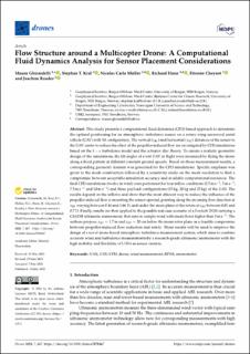
| dc.description.abstract | This study presents a computational fluid dynamics (CFD) based approach to determine the optimal positioning for an atmospheric turbulence sensor on a rotary-wing uncrewed aerial vehicle (UAV) with X8 configuration. The vertical (𝑧𝐵𝐹) and horizontal (𝑥𝐵𝐹) distances of the sensor to the UAV center to reduce the effect of the propeller-induced flow are investigated by CFD simulations based on the 𝑘−𝜖 turbulence model and the actuator disc theory. To ensure a realistic geometric design of the simulations, the tilt angles of a test UAV in flight were measured by flying the drone along a fixed pattern at different constant ground speeds. Based on those measurement results, a corresponding geometry domain was generated for the CFD simulations. Specific emphasis was given to the mesh construction followed by a sensitivity study on the mesh resolution to find a compromise between acceptable simulation accuracy and available computational resources. The final CFD simulations (twelve in total) were performed for four inflow conditions (2.5 m s−1, 5 m s−1, 7.5 m s−1 and 10 m s−1) and three payload configurations (15 kg, 20 kg and 25 kg) of the UAV. The results depend on the inflows and show that the most efficient way to reduce the influence of the propeller-induced flow is mounting the sensor upwind, pointing along the incoming flow direction at 𝑥𝐵𝐹 varying between 0.46 and 1.66 D, and under the mean plane of the rotors at 𝑧𝐵𝐹 between 0.01 and 0.7 D. Finally, results are then applied to the possible real-case scenario of a Foxtech D130 carrying a CSAT3B ultrasonic anemometer, that aims to sample wind with mean flows higher than 5 m s−1. The authors propose 𝑥𝐵𝐹=1.7 m and 𝑧𝐵𝐹=20 cm below the mean rotor plane as a feasible compromise between propeller-induced flow reduction and safety. These results will be used to improve the design of a novel drone-based atmospheric turbulence measurement system, which aims to combine accurate wind and turbulence measurements by a research-grade ultrasonic anemometer with the high mobility and flexibility of UAVs as sensor carriers. | en_US |
| dc.language.iso | eng | en_US |
| dc.publisher | MDPI | en_US |
| dc.rights | Navngivelse 4.0 Internasjonal | * |
| dc.rights.uri | http://creativecommons.org/licenses/by/4.0/deed.no | * |
| dc.title | Flow Structure around a Multicopter Drone: A Computational Fluid Dynamics Analysis for Sensor Placement Considerations | en_US |
| dc.type | Journal article | en_US |
| dc.type | Peer reviewed | en_US |
| dc.description.version | publishedVersion | en_US |
| dc.rights.holder | Copyright 2023 The Author(s) | en_US |
| dc.source.articlenumber | 467 | en_US |
| cristin.ispublished | true | |
| cristin.fulltext | original | |
| cristin.qualitycode | 1 | |
| dc.identifier.doi | 10.3390/drones7070467 | |
| dc.identifier.cristin | 2171023 | |
| dc.source.journal | Drones | en_US |
| dc.identifier.citation | Drones. 2023, 7 (7), 467. | en_US |
| dc.source.volume | 7 | en_US |
| dc.source.issue | 7 | en_US |
Files in this item
This item appears in the following Collection(s)
-
Geophysical Institute [1191]
-
Registrations from Cristin [9688]

Except where otherwise noted, this item's license is described as Navngivelse 4.0 Internasjonal